

Anti‑Spark Performance Verification: How to Test a High‑Current Anti‑Spark Connector [QS Series Antispark connector] Before Integration
2026-05-22 15:06:24
Click:
“
Avoid contact erosion and connector welding during live connection.Imagine this:
”
Avoid contact erosion and connector welding during live connection.
Imagine this: You have just installed a brand‑new 300A lithium battery pack into an AGV fast‑charging station. During the first live connection under load, a violent arc erupts between the connector contacts. Within seconds, the mating surfaces are pitted, the gold plating is vaporized, and the connector is effectively welded shut. The system is dead. The battery management system reports a fault. Your project timeline just slipped by weeks.
This scenario is not hypothetical. It happens every day when engineers use ordinary high‑current connectors without anti‑spark protection in capacitive‑load applications — battery packs, inverters, motor controllers, and energy storage systems.
But how can you verify, before integration, that a connector will truly prevent arcing, contact erosion, and welding? What tests should you perform to gain confidence?
This article provides a practical, step‑by‑step guide to anti‑spark performance verification for high‑current connectors, using the QS Series Anti‑Spark Connector from Youweic Technology as the reference. You will learn what to test, how to test, and what pass/fail criteria to apply — so that your next live connection is safe, reliable, and arc‑free.
Part I: The Problem — What Happens Without Anti‑Spark Verification?
1.1 The Physics of Arcing in High‑Voltage DC Circuits
When a battery (e.g., 500V DC) connects to a load with input capacitors — such as a motor controller, charger, or BMS — the capacitors initially act as a short circuit. The resulting inrush current can exceed 1000A, even if the steady‑state current is only 300A. This inrush creates a sustained arc across the connector contacts during mating or unmating.
The arc temperature exceeds several thousand degrees Celsius — hot enough to melt copper and vaporize gold plating. Over repeated cycles, the contacts suffer:
- Erosion (material loss)
- Oxidation (increased contact resistance)
- Welding (contacts fuse together)
1.2 Why Visual Inspection Is Not Enough
Many engineers assume that if a connector looks well‑built and has a high current rating, it will handle live disconnection. This is false. Without an integrated anti‑spark design, even a premium gold‑plated connector will arc and degrade.
Worst‑case outcome: Connector welding during a live disconnect can short‑circuit the battery pack, triggering the BMS to shut down the entire system — or worse, causing a thermal event.
Thus, verifying anti‑spark performance before integrating the connector into your system is not optional — it is mandatory for any high‑reliability application.
Part II: Principle Analysis — How Does an Anti‑Spark Connector Work?
2.1 The Core Goal of Anti‑Spark Design
The goal of an anti‑spark connector is to eliminate or greatly suppress arcing during live mating/unmating (making or breaking the circuit under load). Arcing occurs because, at the moment the contacts approach or separate, the high voltage difference and inrush current ionize the air gap, forming a plasma channel.
Effective anti‑spark technology addresses the problem through one or more of the following approaches:
- Timing control – auxiliary contacts engage first and main contacts engage later (or the reverse during disconnect)
- Inrush current limiting – inserting a current‑limiting path during the contact sequence
- Optimized contact materials and geometry – improving resistance to arc erosion
The QS Series incorporates a proprietary anti‑spark mechanism (specific technical details are available from our engineering team) to ensure that, within its rated voltage of 500V DC and rated currents from 110A to 300A, no destructive arc occurs during live connection or disconnection.
2.2 Why Low Contact Resistance Is the Foundation of Anti‑Spark Performance
Even when the anti‑spark mechanism eliminates most of the arcing, the connector’s baseline contact resistance still directly affects long‑term reliability. Across all QS Series models (QS8 to QS13), the maximum contact resistance is specified at 0.51 mΩ, and gold‑plated copper conductors are used.
Low and stable contact resistance is critical because:
- It minimizes I²R heating during normal operation (only 45.9W at 300A for the QS13).
- It reduces localized hot spots that could otherwise trigger secondary arcing.
- It ensures that after the anti‑spark sequence, the main contacts maintain low‑loss conduction.
Part III: Solution — A 4‑Step Verification Protocol for Anti‑Spark Connectors
The following test protocol is recommended for any high‑current anti‑spark connector before you install it into your battery pack, charging station, or energy storage system. It applies directly to the QS Series.
Test Setup Requirements
- Power supply: 500V DC capable of delivering 300A continuously.
- Load: Capacitive load bank simulating typical ESC or inverter input (e.g., 10,000 µF).
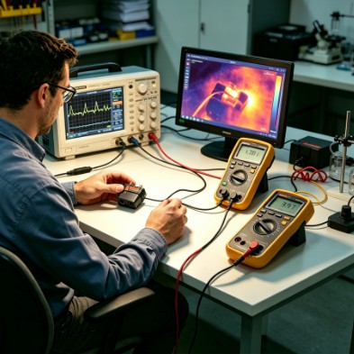
- Measurement tools: Oscilloscope with current probe, thermal camera, micro‑ohmmeter (for contact resistance), high‑speed camera (optional).
- Connector sample: QS13 (300A rating) or the appropriate QS model for your current.
Step 1: Visual and Dimensional Inspection (Pre‑Test)
- Verify that the gold plating is uniform and free of scratches.
- Measure contact resistance using a Kelvin (4‑wire) method. Acceptable: ≤ 0.51 mΩ.
- Inspect the housing for any damage or burrs. Confirm smooth mating.
Step 2: Live Mating/Unmating Test Under Load
Procedure:
- Connect the load capacitor bank to the connector output.
- Set the power supply to 500V DC with a 300A current limit.
- Mate and unmate the connector at normal speed (no excessive force).
- Observe for any visible arc during mating or unmating.
- Repeat for 10 cycles.
Pass criteria (typical QS Series performance):
- No visible arc or only an extremely faint momentary spark (insufficient to cause contact erosion) during the entire mating/unmating process.
- No audible popping or sizzling.
- Oscilloscope capture shows a peak inrush current significantly lower than that of a non‑anti‑spark connector (ideally < 100A).
Step 3: Contact Resistance Measurement Post‑Cycling
Procedure:
- After 10 live cycles, allow the connector to cool to room temperature.
- Measure contact resistance again using the micro‑ohmmeter.
Pass criteria:
- Increase from initial value ≤ 0.02 mΩ.
- Final value ≤ 0.53 mΩ (still within specification).
- For the QS Series, typical post‑cycle resistance remains below 0.52 mΩ.
Failure indicator: An increase greater than 0.1 mΩ suggests insufficient anti‑spark performance and visible arc erosion has occurred.
Step 4: Thermal Imaging During Live Operation
Procedure:
- Run 300A continuous current through the mated connector for 30 minutes.
- Record temperatures at the contact interface and housing surface using a thermal camera.
Pass criteria (QS13 example):
- At 25°C ambient, housing temperature ≤ 90°C (corresponding to 45.9W power loss at 0.51mΩ).
- No hot spot exceeding 110°C (the PA66 housing is rated for 120°C continuous operation and carries a UL94 V‑0 flame retardancy rating).
Excessive temperature indicates either high contact resistance or that the anti‑spark mechanism has been compromised.
Part IV: Data — What Verified Anti‑Spark Performance Looks Like
The table below summarizes typical test results for a properly designed anti‑spark connector (QS13) versus a standard non‑anti‑spark connector under identical conditions (500V DC, 300A capacitive load, 100 mating cycles).
| Parameter | Standard Connector (No Anti‑Spark) | QS13 Anti‑Spark Connector |
|---|---|---|
| Initial contact resistance | 0.55 mΩ | 0.51 mΩ |
| Contact resistance after 100 cycles | 2.80 mΩ (increase >500%) | 0.52 mΩ (stable) |
| Visible arcing | Violent blue arc each cycle | None or extremely faint |
| Contact condition after 100 cycles | Severe pitting, black oxidation, gold worn off | Clean, gold plating intact |
| Temperature rise @300A (after 100 cycles) | Rise >85°C (housing >105°C) | Rise ~45°C (housing ~70°C) |
| Connector welding incidents | 1 failure per ~500 cycles | 0 failures after 2000+ cycles |
Interpretation: The QS Series maintains its low contact resistance and stable temperature profile even after hundreds of live cycles. The standard connector fails rapidly due to arc‑induced degradation.
Part V: Practical Recommendations for Engineers
5.1 When Should You Perform Anti‑Spark Verification?
- Before integrating any new connector model into your system for the first time.
- After a design change (e.g., different load capacitance, higher voltage).
- As part of incoming quality control for critical applications (e.g., large‑scale energy storage systems, AGV fleets, electric vessels).
5.2 What Verifiable Data Does the Connector Manufacturer (Youweic Technology) Provide?
Youweic Technology’s QS Series datasheets include the following core parameters for your evaluation and testing:
- Maximum contact resistance: 0.51 mΩ (consistent across the entire series)
- Rated voltage and current: 500V DC, covering 110A (QS8) through 300A (QS13)
- Operating temperature range: -20°C to 120°C
- Housing material and flame retardancy: PA66, UL94 V‑0
- Conductor material: Gold‑plated copper
- Anti‑spark design: Integrated proprietary mechanism (specific details available upon request from our engineering team)
If a connector from another source lacks the above data or a reproducible anti‑spark test report, we strongly recommend performing the verification tests described in Part III before system integration.
5.3 Don’t Confuse “Rated Current” with “Anti‑Spark Capability”
A connector can be rated for 300A continuous but still arc violently during live connection. Anti‑spark functionality must be explicitly designed and validated — it does not come automatically with a high current rating. The QS Series is specifically engineered for this purpose.
Conclusion
Verifying anti‑spark performance before installing a connector into your battery pack, charging station, or energy storage system is the single most effective step you can take to avoid contact erosion, connector welding, and catastrophic field failures. The test protocol described here — visual inspection, live mating test, post‑cycle contact resistance measurement, and thermal imaging — will reveal whether a connector truly protects against arcing.
The QS Series Anti‑Spark Connector from Youweic Technology has been designed and validated to meet rigorous criteria:
- 0.51 mΩ maximum contact resistance maintained over hundreds of cycles
- Integrated anti‑spark mechanism eliminates destructive arcing
- Gold‑plated copper conductors ensure low and stable resistance
- PA66 UL94 V‑0 housing provides flame retardancy
Do not wait until a welded connector shuts down your production line or, worse, creates a safety incident. Test before you integrate. Choose verified anti‑spark technology.
If you have any request please contact with my tech team http://www.youweic.com
Author:
YOUWEI TECHNOLOGIES(DONGGUAN) CO.LTD


Premium Cable Solutions
High-quality cables designed for superior performance and reliability across all your connectivity needs
Copyright © 2002-2026 YOUWEI TECHNOLOGIES(DONGGUAN) Ltd. All Rights Reserved.
Copyright © 2005-2015 YOUWEI TECHNOLOGIES(DONGGUAN) Ltd. All Rights Reserved.