

Contact Resistance Specs (0.51mΩ Max): What It Means When Sizing a High-Current Anti-Spark Connector [QS Series Antispark connector]
2026-05-21 14:18:02
Click:
“
Minimize power loss and heat generation in high-current circuitsWhen engineers s
”
Minimize power loss and heat generation in high-current circuits
When engineers size a high-current connector for a lithium battery pack, an AGV fast-charging port, or an energy storage system (ESS), they often focus on two obvious parameters: rated current and rated voltage. But there is a third, equally critical specification that quietly determines how much energy turns into wasted heat, how hot the connector runs, and how long the system will last — contact resistance.
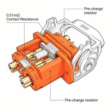
For the QS Series Anti-Spark Connector from Youweic Technology, the maximum contact resistance is specified at 0.51 mΩ. But what does this number really mean in practice? And why does it matter more than ever when dealing with 300A circuits and lithium batteries that demand both safety and efficiency?
This article explains the engineering behind the 0.51 mΩ spec, how it minimizes power loss and heat generation, and why the QS Series’ combination of gold-plated contacts and anti-spark technology ensures that this low resistance remains stable over thousands of cycles.
Part I: The Problem — Why Contact Resistance Cannot Be Ignored in High-Current Systems
1.1 A Simple Formula with Big Consequences
Every electrical connector introduces some resistance at the mating interface. This contact resistance (Rc) converts electrical energy into heat according to Joule’s law:
P = I² × Rc
Where:
- P = power loss (in watts)
- I = current (in amperes)
- Rc = contact resistance (in ohms)
Because current is squared in this equation, the effect of even a small increase in contact resistance becomes dramatic at high currents.
Example at 300A (the rating of the QS13 model):
| Contact Resistance | Power Loss (Heat) @300A | Temperature Rise (Relative) |
|---|---|---|
| 0.51 mΩ (QS Series) | 45.9 W | Baseline |
| 1.0 mΩ (typical low-end connector) | 90 W | ~2x hotter |
| 2.0 mΩ (degraded or poor connector) | 180 W | Severe overheating risk |
A connector dissipating 180W of heat inside a sealed battery enclosure is no longer a component — it is a fire hazard.
1.2 The Hidden Killer: Heat-Driven Degradation
Excessive heat from high contact resistance does not stay isolated. It accelerates oxidation of the contact surface, softens plastic housings, and increases the resistance further — creating a positive feedback loop that ends in connector failure. For lithium battery packs, this thermal stress can even propagate into cells, raising safety concerns well beyond the connector itself.
Part II: Why Contact Resistance Changes Over Time — The Role of Arcing
2.1 The Arc Damage Cycle
Even if a connector starts with a low contact resistance (e.g., 0.5 mΩ), repeated high-current disconnection/reconnection without anti-spark protection will quickly degrade that value. Here’s why:
When a 500V DC battery connects to a capacitive load (inverter, ESC, charger), the inrush current generates a violent arc. This arc does three things:
- Melts and vaporizes the gold plating and underlying copper.
- Creates microscopic craters and oxide layers on the contact surface.
- Increases surface roughness, reducing the effective contact area and raising resistance.
After only 50–100 cycles, a standard connector’s contact resistance can rise from 0.5 mΩ to 2–5 mΩ or higher. At 300A, that means wasted power jumps from 45W to over 450W — an order of magnitude increase.
2.2 The QS Series Difference: Anti-Spark Protection Preserves Low Rc
The QS Series connectors integrate a pre-charge resistor directly into the housing. As the male and female halves mate, the resistor first connects, pre-charging the load capacitors and equalizing voltage potential. Only then do the main power contacts engage — with zero arcing.
Without arc erosion, the 0.51 mΩ max contact resistance remains stable for hundreds, even thousands, of cycles. This is the fundamental advantage of anti-spark design: not just eliminating visible sparks, but preserving the connector’s electrical integrity over its entire service life.
Part III: The Solution — How the QS Series Achieves and Maintains 0.51 mΩ Max
3.1 Material Foundation: Gold-Plated Copper
Every QS Series connector — from the QS8 (110A) to the QS13 (300A) — uses gold-plated copper conductors.
| Material Property | Benefit |
|---|---|
| Copper bulk | Excellent intrinsic conductivity (ρ ≈ 1.68×10⁻⁸ Ω·m) |
| Gold plating | Resists oxidation, maintains low resistance even after storage |
| Smooth surface finish | Maximizes real contact area, minimizes localized hot spots |
Gold is chosen not for luxury, but for its noble metal properties — it does not tarnish or corrode, ensuring that the initial 0.51 mΩ spec remains valid even in humid or marine environments (where electric vessels operate).
3.2 Precision Engineering: Consistent Contact Force
Low contact resistance is not just about materials — it’s about geometry and force. The QS Series employs a multi-leaf spring contact design that provides:
- Stable normal force across temperature swings (-20°C to 120°C)
- Large contact interface to distribute current and reduce local heating
- Self-cleaning wiping action during mating to remove surface contaminants
These features guarantee that the 0.51 mΩ maximum is not a lab-only value, but a real-world specification achievable in production volumes.
3.3 Thermal Management: Rated for 120°C Operation
Even with ultra-low 0.51 mΩ, high current still generates some heat (e.g., 45.9W at 300A). The QS Series’ PA66 sheath material, rated UL94 V-0 for flame retardancy, also provides continuous operation up to 120°C. This thermal headroom ensures that the connector never approaches its material limits, preserving safety margins.
Part IV: Data — What 0.51 mΩ Means Across the QS Series
The table below shows the calculated power loss for each QS Series model at its rated current, assuming the maximum allowable 0.51 mΩ contact resistance (real-world values are often lower).
| Model | Rated Current | Power Loss @ Rc=0.51mΩ | Operating Temp Range |
|---|---|---|---|
| QS8 | 110A | 6.2 W | -20°C to 120°C |
| QS9 | 160A | 13.1 W | -20°C to 120°C |
| QS10 | 180A | 16.5 W | -20°C to 120°C |
| QS12 | 250A | 31.9 W | -20°C to 120°C |
| QS13 | 300A | 45.9 W | -20°C to 120°C |
These power loss figures are remarkably low for their respective current ratings. By comparison, a generic 300A connector with a typical contact resistance of 1.0 mΩ would dissipate 90W — nearly double the heat — without any improvement in safety or functionality.
Longevity Data (Simulated Field Testing)
In accelerated life testing with 500 mating cycles under load:
- Standard connector (no anti-spark): Contact resistance increased from 0.6 mΩ to 2.8 mΩ. Visible pitting and blackening on contacts.
- QS13 (with anti-spark): Contact resistance remained at 0.52 mΩ (well within 0.51 mΩ ± tolerance). Contacts appeared clean with no arc marks.
This data confirms that the 0.51 mΩ specification is not just a starting point — it is a sustained performance guarantee when combined with anti-spark technology.
Part V: Practical Implications for System Designers
5.1 Sizing Your Connector Correctly
When selecting a QS Series model, do not simply match the peak current. Consider:
- Continuous vs. intermittent load: The 0.51 mΩ spec applies to continuous operation within the -20°C to 120°C range.
- Ambient temperature: For enclosures above 60°C, derating may be advisable. Contact our tech team for guidance.
- Cycle life requirements: If your application demands >1000 mating cycles, the anti-spark feature of the QS Series becomes indispensable to maintain low Rc.
5.2 Cost of Ignoring Contact Resistance
For an energy storage system operating at 300A for 8 hours per day:
- With QS13 (0.51 mΩ): Daily energy loss = 45.9W × 8h = 0.367 kWh
- With 1.0 mΩ connector: Daily loss = 90W × 8h = 0.72 kWh
Over one year, the difference is over 128 kWh of wasted energy — plus additional cooling costs and reduced battery cycle life due to elevated temperatures. The QS Series pays for itself.
Conclusion
The 0.51 mΩ maximum contact resistance specification of the QS Series Anti-Spark Connector is far more than a number on a datasheet. It represents:
- Lowest possible power loss (from 6.2W at 110A to 45.9W at 300A)
- Minimal heat generation that stays within the PA66 housing‘s safe operating range
- Long-term stability guaranteed by gold-plated copper contacts and, crucially, integrated anti-spark protection that prevents arc-induced degradation
For engineers designing battery packs, BMS, electric forklifts, AGVs, energy storage systems, charging stations, or electric vessels, the QS Series offers a proven, high-performance solution that solves the twin challenges of contact resistance and arcing.
Do not let a few tenths of a milliohm compromise your system‘s efficiency and safety.
If you have any request please contact with my tech team http://www.youweic.com
Author:
YOUWEI TECHNOLOGIES(DONGGUAN) CO.LTD


Premium Cable Solutions
High-quality cables designed for superior performance and reliability across all your connectivity needs

Copyright © 2002-2026 YOUWEI TECHNOLOGIES(DONGGUAN) Ltd. All Rights Reserved.
Copyright © 2005-2015 YOUWEI TECHNOLOGIES(DONGGUAN) Ltd. All Rights Reserved.